Uplift capacity
150 te ULS

Anchors tested at full scale for tensioning, maximum load and fatigue, with instrumentation and control throughout.
The Load Test Frame & Control System sits at the validation end of the Raptor range. The other systems install anchors; this one establishes what those anchors will hold.
Operators need evidence that an anchor will behave predictably under genuine offshore loads. That requirement is sharpest in floating wind and tidal work, and anywhere else that marine energy levels run high.
The frame was built for that job. It applies tensioning, maximum load and fatigue regimes to a complete anchor at working scale, reproducing the loading an installation would see over years in service.
Installation on its own proves little. The value lies in the record that comes with it: measured performance, dependable engineering data, and a documented view of long-term integrity and operational capability.
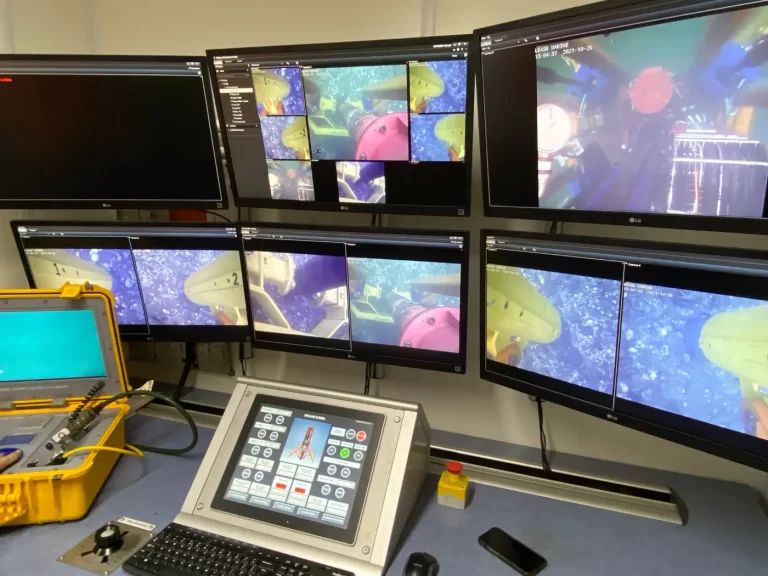
Monitoring, instrumentation and control are integral to the system, so load, displacement and overall behaviour are captured in fine detail for the full duration of a test, giving:
The same capability shortens development. Designs can be proven, adjusted and demonstrated before anyone commits to large-scale deployment. On paper this is test equipment; in practice it is one of the enabling technologies behind safe, efficient scaling of offshore renewable infrastructure.
| Load Frame | 150 te uplift capacity ULS |
| HPU | 18.5 kW EHPU |
| SCADA System | High frequency logging |
| Sensor Beams | Two no. frames |
| Load Links | Two sets |
| Transport | 2 no. 20 ft ISO containers |
| Lateral Link | 150 te capacity cylinder |
| Documentation | Full engineering pack |
| Material | Steel |
| Weight | 5.20 te |
| Setup for testing | |
| Length | 5.88 m |
| Width | 5.15 m |
| Height | 2.94 m |
| Stowed for transport | |
| Length | 4.03 m |
| Width | 2.01 m |
| Height | 1.81 m |
| Test Types | ULS & FLS |
| Load Outputs | Dual load cylinders |
| Rated Pull | Ram pull 150 te |
| Three Phase Input | 400 V @ 50 Hz |
| Cooling | Air |
| HPU Power | 18.5 kW |
| HPU Pressure | 320 bar |
| HPU Flow | 28 lpm |
| Oil Type | Panolin S4 HLP Synth 32 |
| Frame & HPU Sensors | Full safety & ops suite |
| Logging Inputs | Up to 32 total |
| Type | Cabinets with AC |
| Safety | Interlocks & shutdowns |
| E-Stops | Multiple on system |
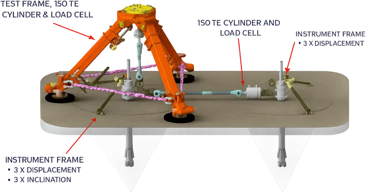
| Displacement | 6 no. |
| Inclination | 3 no. |
| Load Cell | 2 no. 150 te pins in links |
| 1 no. 100 te annular |
The evidence base that lets offshore renewable infrastructure scale safely.